
Building Your Own Thread Border Router with ESP32s
Why build your own Thread Border Router when so many devices already include one? What started as a simple home automation need took me much further than expected: Thread, OpenThread, ESP32-S3, ESP32-C6, RCP, external antennas, network diagnostics... This is the story of a Border Router I built, modified and broke several times before finally arriving at a solution I can truly understand, observe and maintain.
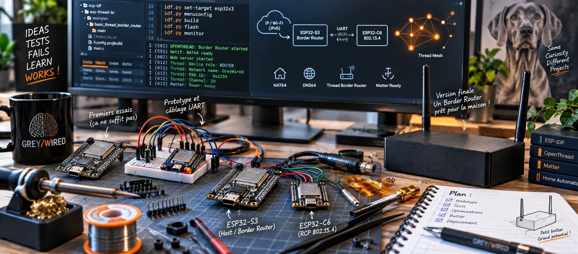
It all started with a lock.
More precisely, a Nuki Smart Lock Pro that I wanted to integrate properly with Home Assistant.
I could have chosen the most obvious solution: Wi-Fi. The lock supports it, Home Assistant does too, and that would probably have solved the problem very quickly.
But a lock runs on a battery.
Maintaining a Wi-Fi connection has an energy cost. Thread was designed precisely for constrained connected devices: low power consumption, IPv6 mesh networking, and the ability for some devices to spend a large part of their time asleep.
For a lock, the reasoning was therefore fairly simple: less energy spent on connectivity potentially means more time between charges.
Choosing Thread made sense.
But it introduced a new piece into the equation.
Home Assistant lives on my IP network. The lock would live on a Thread network. To make the two communicate, I needed a Thread Border Router.
I could have bought one.
Obviously, that is not what I did.
Why build your own Thread Border Router?
That is probably the first question to ask.
Thread Border Routers already exist. They are built into many Apple, Google, Amazon, Home Assistant and other home-automation products and gateways.
If your only goal is to connect a few Matter over Thread devices and never worry about what happens underneath, building your own probably has little value.
But if you want to understand, observe or modify your Thread network, things become much more interesting.
Understand
Building the Border Router quickly forces you to understand what is actually happening underneath Matter and Thread.
You discover, among other things, the separation between:
- the conventional IP network;
- the Thread network;
- the Border Router;
- the host processor;
- the IEEE 802.15.4 radio;
- the RCP --- Radio Co-Processor;
- Spinel;
- and the Operational Dataset that defines the identity of the Thread network.
Thread becomes much less magical.
Observe and diagnose
A Border Router you control also gives you access to OpenThread tools.
A few commands already reveal a great deal:
ot state
ot dataset active
ot child table
ot neighbor table
ot router table
You can see the Border Router's children, its neighbors, link quality, RSSI, RLOC16 values, and the state of the network.
What initially looks like a simple gateway then becomes a genuine Thread diagnostic tool.
Control the radio
This is also one of the major hardware advantages of my setup.
By using an ESP32-C6 as the radio co-processor, I control its firmware as well as its RF implementation.
In my case, the XIAO ESP32-C6 makes it possible to use an external antenna for the IEEE 802.15.4 radio.
This obviously does not mean that an external antenna magically increases the range of a Thread network: communication remains bidirectional, and remote devices must also be able to answer.
But it does make it possible to optimize antenna placement, move it away from an enclosure or metal mass and, more generally, gain much better control over the Border Router's RF side.
Control the firmware
The RCP is not a black box.
I can build its firmware, modify it and instrument it.
Later, I will even show that the host processor can automatically maintain the firmware of this radio co-processor.
The cost
Finally, the hardware investment is almost negligible.
Two small ESP32 boards, a few wires, a power supply and optionally two external antennas are enough.
For a few dozen euros, you get not only a Thread Border Router, but also a platform for experimenting with and analyzing the network.
First idea: one ESP32-C6 should be enough
After some research, my first instinct was to try building the Thread Border Router around a single ESP32-C6.
The choice seemed obvious.
The C6 has both Wi-Fi and an IEEE 802.15.4 radio compatible with Thread.
On paper:
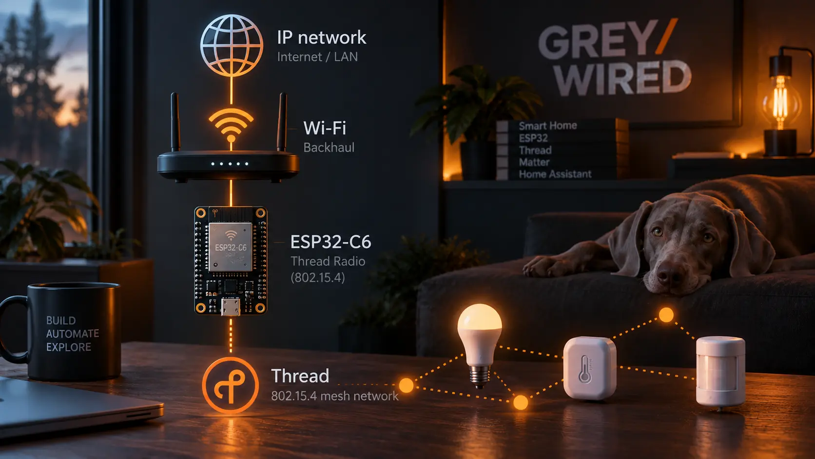
Why use two microcontrollers when one appears to provide all the required interfaces?
And technically, it worked.
I obtained a working Thread Border Router.
It would therefore be incorrect to claim that a Border Router built solely around an ESP32-C6 does not work.
However, the experience did not entirely convince me.
In particular, I was seeing an almost daily problem that I could not explain. The whole system also seemed somewhat unresponsive, although that last point remains a completely empirical observation: I had not made any measurements to quantify it.
More importantly, the more I explored the OpenThread and Espressif ecosystem, the more the separation between a host processor and a dedicated radio co-processor seemed to be the architecture to favor.
And there was a more fundamental problem.
The system was a big black box.
When something went wrong, determining whether the problem came from Wi-Fi, Thread, radio coexistence or my implementation quickly became complicated.
To investigate properly, I had to go back to a USB cable, connect the C6 to a PC and watch its console.
Very convenient on a workbench.
Much less so for a device intended to run 24 hours a day in a house.
The C6 had been blamed a little too quickly
I later discovered the cause of my famous daily problem.
My Wi-Fi access point deliberately restarts every night, at around 03:00.
The basic implementation I was using apparently did not handle this scenario properly: after the access point temporarily disappeared, the connection was not restored as I expected.
So the C6 had not really "crashed".
It had lost its Wi-Fi backhaul and had not recovered it properly.
I discovered this later, but I did not return to the C6-only architecture.
By then, I was no longer simply looking for a Thread Border Router that worked.
I wanted a Thread Border Router whose behavior I could understand when it did not work.
Two chips instead of one
That was when I decided to separate the roles.
My choice of hardware was extremely pragmatic: I had an ESP32-S3 and a XIAO ESP32-C6 at hand.
This is not necessarily the most conventional combination for building a Thread Border Router.
But it is technically supported, and there was no reason not to try.
The principle then becomes:
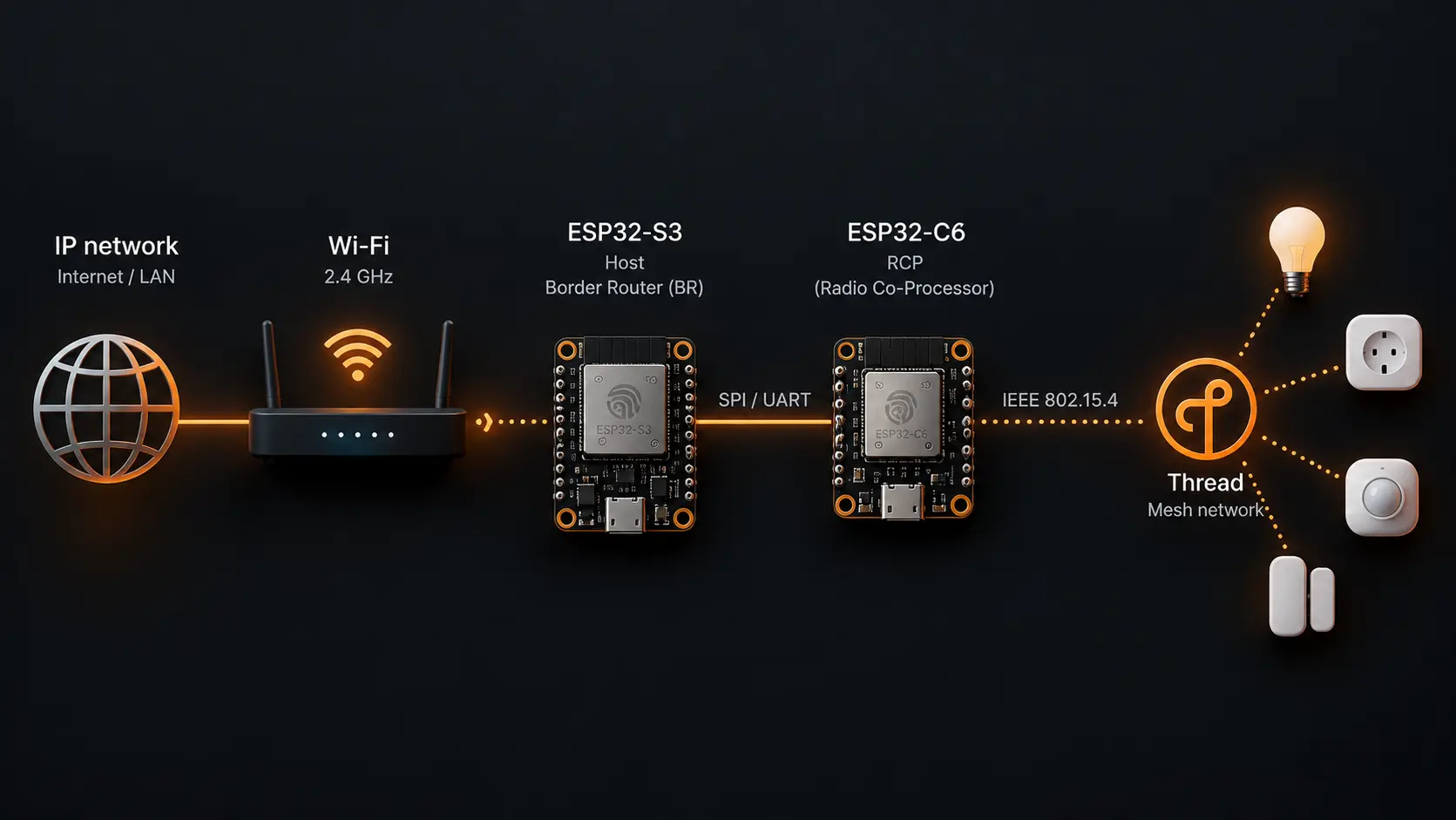
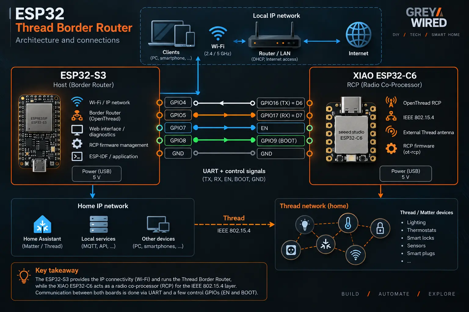
The S3 handles the IP network and the Border Router functions.
The C6 becomes much more specialized: it handles the IEEE 802.15.4 radio and communicates with the host through Spinel.
Before building the Border Router, I therefore had to start by turning the C6 into an RCP.
Building the ESP32-C6 RCP firmware
Before going any further, a word about ESP-IDF. The Espressif IoT
Development Framework is Espressif's official development framework for
ESP32 microcontrollers. Among other things, it provides the OpenThread
components and the ot_rcp example used here.
The framework is available from the official repository: https://github.com/espressif/esp-idf.
For this project, I used ESP-IDF 5.5.5 on Windows 11 with
PowerShell. I am deliberately specifying the version: ESP-IDF,
OpenThread and esp-thread-br are still evolving quickly, and a
different version may present slightly different menus or options.
The RCP example is included directly in ESP-IDF:
examples\openthread\ot_rcp
On Windows, I start by loading the ESP-IDF environment:
cd C:\esp\esp-idf
.\export.ps1
Then:
cd examples\openthread\ot_rcp
idf.py set-target esp32c6
idf.py menuconfig
RCP configuration
The required configuration is actually quite simple.
In OpenThread RCP Example, I choose to define the UART pins manually:
[*] Configure RCP UART pin manually
(17) The number of RX pin
(16) The number of TX pin
Which corresponds in my sdkconfig to:
CONFIG_OPENTHREAD_UART_PIN_MANUAL=y
CONFIG_OPENTHREAD_UART_RX_PIN=17
CONFIG_OPENTHREAD_UART_TX_PIN=16
The C6 will therefore communicate with its host through:
C6 RX = GPIO17 = D7 on the XIAO ESP32-C6
C6 TX = GPIO16 = D6 on the XIAO ESP32-C6
This is a useful detail when wiring: menuconfig uses the GPIO
numbers, while the XIAO pinout identifies those same pins as D7 and
D6.
The example is configured to expose the RCP over UART:
CONFIG_OPENTHREAD_RCP_UART=y
# CONFIG_OPENTHREAD_RCP_SPI is not set
The C6 directly uses its own IEEE 802.15.4 radio:
CONFIG_OPENTHREAD_RADIO=y
CONFIG_OPENTHREAD_RADIO_NATIVE=y
Keeping the console independent from the RCP
I also configure the console on the USB Serial/JTAG controller:
Component config → ESP System Settings → Channel for console output
(X) USB Serial/JTAG Controller
Which gives:
CONFIG_ESP_CONSOLE_USB_SERIAL_JTAG=y
CONFIG_ESP_CONSOLE_USB_SERIAL_JTAG_ENABLED=y
This separation is particularly convenient:
GPIO16 / GPIO17
       │
       └── Spinel / communication with the S3

USB Serial/JTAG
       │
       └── C6 logs and diagnostics
I can therefore instrument and observe the C6 without ever interfering with the link used by the RCP.
Flash configuration
On my XIAO ESP32-C6, the configuration I used is:
Flash SPI mode  : DIO
Flash SPI speed : 80 MHz
Flash size      : 2 MB
These values correspond to my board. They should not be considered a universal configuration for every ESP32-C6-based board.
The screenshots below show the main menuconfig screens used to build
this RCP firmware. They provide a visual check of the configuration
before starting the build.


Using the XIAO ESP32-C6 external antenna
This step is entirely optional. It is only relevant if you actually connect an external antenna to the XIAO ESP32-C6 connector.
If you use the board's built-in antenna, no firmware modification is required: you can skip directly to Build and flash.
In my case, I chose to use an external antenna, which requires explicitly selecting the corresponding RF path in the firmware.
At this point, I could already build a working RCP.
But the XIAO ESP32-C6 has a particularly interesting feature for my project: a connector for an external antenna.
Simply connecting an antenna to the connector is not enough, however.
The RF path must also be selected in software.
In:
examples\openthread\ot_rcp\main\esp_ot_rcp.c
I add:
#include "driver/gpio.h"
Then:
/*
 * XIAO ESP32-C6 RF switch
 *
 * GPIO3  = RF switch control
 * GPIO14 = antenna selection
 *
 * GPIO14 HIGH selects the external antenna.
 */
static void xiao_use_external_antenna(void)
{
    gpio_set_direction(GPIO_NUM_3, GPIO_MODE_OUTPUT);
    gpio_set_level(GPIO_NUM_3, 0);

    gpio_set_direction(GPIO_NUM_14, GPIO_MODE_OUTPUT);
    gpio_set_level(GPIO_NUM_14, 1);

    ESP_LOGI(TAG, "XIAO ESP32-C6 external antenna selected");
}
And I call this function immediately at the beginning of app_main():
void app_main(void)
{
    /*
     * Select XIAO external antenna first.
     */
    xiao_use_external_antenna();

    /* ... */
}
The result is therefore:
GPIO3  = LOW
GPIO14 = HIGH
        │
        └── external antenna selected
Build and flash
I can now build the RCP:
idf.py build
Then, for this first installation, flash it directly.
On Windows, I can first list the available serial ports to identify the XIAO:
Get-CimInstance Win32_SerialPort |
    Select-Object DeviceID, Name
For example:
DeviceID Name
-------- ----
COM4     USB Serial Device (COM4)
Then simply use the corresponding port:
idf.py -p COM4 flash monitor
Another option is to open Windows Device Manager → Ports (COM & LPT). If in doubt, unplugging and reconnecting the XIAO will usually make the relevant port immediately obvious.
At startup, my modification notably lets me verify:
XIAO ESP32-C6 external antenna selected
The RCP is ready.
And the location of its build directory is worth remembering:
C:\esp\esp-idf\examples\openthread\ot_rcp\build
I will show later that this directory plays an important role in my final architecture.
Instrumenting the RCP
This step is not required for the Border Router to work.
During my investigations, however, I added a few diagnostics to the C6 firmware.
In particular, I logged the reason for the last reset, and a task produced a heartbeat every 60 seconds containing uptime, free memory and the minimum free memory observed.
The diagnostics were deliberately sent to the ESP-IDF USB console and never over the RCP UART.
This instrumentation is therefore not required for the final procedure, but it illustrates one of the advantages of building your own system: when something behaves strangely, I can instrument it all the way down to the radio co-processor.
Ironically, this also helped me gradually clear the C6 of suspicion in my daily disconnection problem.
First S3 + C6 version
With the C6 firmware ready, it now needed a host.
For this first version, I started from the ot_br example supplied with
ESP-IDF and built it for the ESP32-S3.
After a few configuration and wiring adjustments, the result was functional.
The S3 handled Wi-Fi, the IP network and the host side of OpenThread. The C6 handled the 802.15.4 radio exclusively.
I then started using a few battery-powered IKEA devices as guinea pigs for experimenting with the Thread network.
I could now query OpenThread, inspect the Border Router's children, its neighbors, the dataset and link quality.
Thread was gradually becoming much less opaque.
The setup worked.
I could have stopped there.
Obviously, that is not what happened.
I just wanted a Web page...
There was still one very practical problem.
Even with my new architecture, investigating the Border Router in depth still too easily meant returning to a serial console.
Yet this system was intended to become a permanent part of the house infrastructure.
I did not want to have to fetch a USB cable and connect a computer every time I wanted to know what my Thread network was doing.
So the next goal was extremely modest: add a small Web status page.
A little information about the Border Router state, the Thread network, and enough data to perform an initial diagnosis from a browser.
While looking for a way to integrate this interface, I came back to
Espressif's esp-thread-br project.
And then came the surprise.
What I thought I needed to develop already existed.
And in a much more complete form.
esp-thread-br: I was reinventing something that already existed
The project had clearly evolved considerably.
The example:
examples/basic_thread_border_router
offered, among other things:
- a Web interface for configuring and querying Thread;
- automatic Border Router startup;
- Wi-Fi management, with the ability to configure the network at deployment time;
- support for external RCPs;
- standalone development kits;
- the option to use an ESP32-C6 as the RCP;
- and even RCP firmware updates performed by the host.
Another interesting possibility is that the firmware does not necessarily have to be prepared with the credentials of the final Wi-Fi network. It can be built and flashed in advance, then configured once installed on its destination network.
That is not the option I chose here, since this Border Router is intended for my own network. But the scenario is interesting: it becomes possible to fully prepare a Border Router for someone else and give them a device they can deploy at home without installing ESP-IDF or recompiling the firmware. This brings the project much closer to a genuinely autonomous device that can be deployed in place.
More interesting still: my S3 + C6 architecture could fit perfectly into this implementation.
My combination might not be the most conventional configuration, but it was supported.
At this point, esp-thread-br seemed mature enough for me to consider
using it as the basis for my permanent Border Router.
There was just one small problem.
My Border Router was already working.
My Thread network existed. My IKEA devices were connected to it.
And replacing the S3 firmware meant deliberately breaking something I had finally managed to get working properly.
Again.
Can the Border Router be replaced without rebuilding the Thread network?
The answer lies in a concept I had gradually learned about: the Operational Dataset.
A Thread network is not simply defined by its name.
Its dataset contains, among other things, the channel, PAN ID, Extended PAN ID, Mesh Local Prefix, Network Key, PSKc, security policy and the other parameters required to identify the network.
Before touching the working Border Router, I therefore started by backing up its dataset:
ot dataset active -x
And also its human-readable representation:
ot dataset active
In my case, it included:
Channel: 11
Ext PAN ID: dead00beef00cafe
Mesh Local Prefix: fdde:ad00:beef:0::/64
Network Name: OpenThread
PAN ID: 0x37dd
And, most importantly, the complete hexadecimal representation returned
by ot dataset active -x.
That little line would allow me to rebuild the new Border Router without creating a new Thread network.
Building the final Border Router
esp-thread-br is an Espressif project separate from ESP-IDF, so it
must be retrieved separately. The official repository is available here:
https://github.com/espressif/esp-thread-br.
In my installation, I placed it directly under C:\esp:
cd C:\esp
git clone --recursive https://github.com/espressif/esp-thread-br.git
The relevant directory structure is therefore:
C:\esp\
├── esp-idf\
│   └── examples\openthread\ot_rcp\build\
│
└── esp-thread-br\
    └── examples\basic_thread_border_router\
After loading the ESP-IDF environment:
cd C:\esp\esp-idf
.\export.ps1
I can enter the Border Router example:
cd C:\esp\esp-thread-br\examples\basic_thread_border_router
and target the ESP32-S3.
My final configuration uses:
CONFIG_IDF_TARGET="esp32s3"
CONFIG_ESP_BR_BOARD_STANDALONE=y
CONFIG_ESP_BR_C6_TARGET=y
CONFIG_OPENTHREAD_BR_AUTO_START=y
CONFIG_OPENTHREAD_BR_START_WEB=y
The S3 can therefore start the Border Router automatically and expose its Web interface.
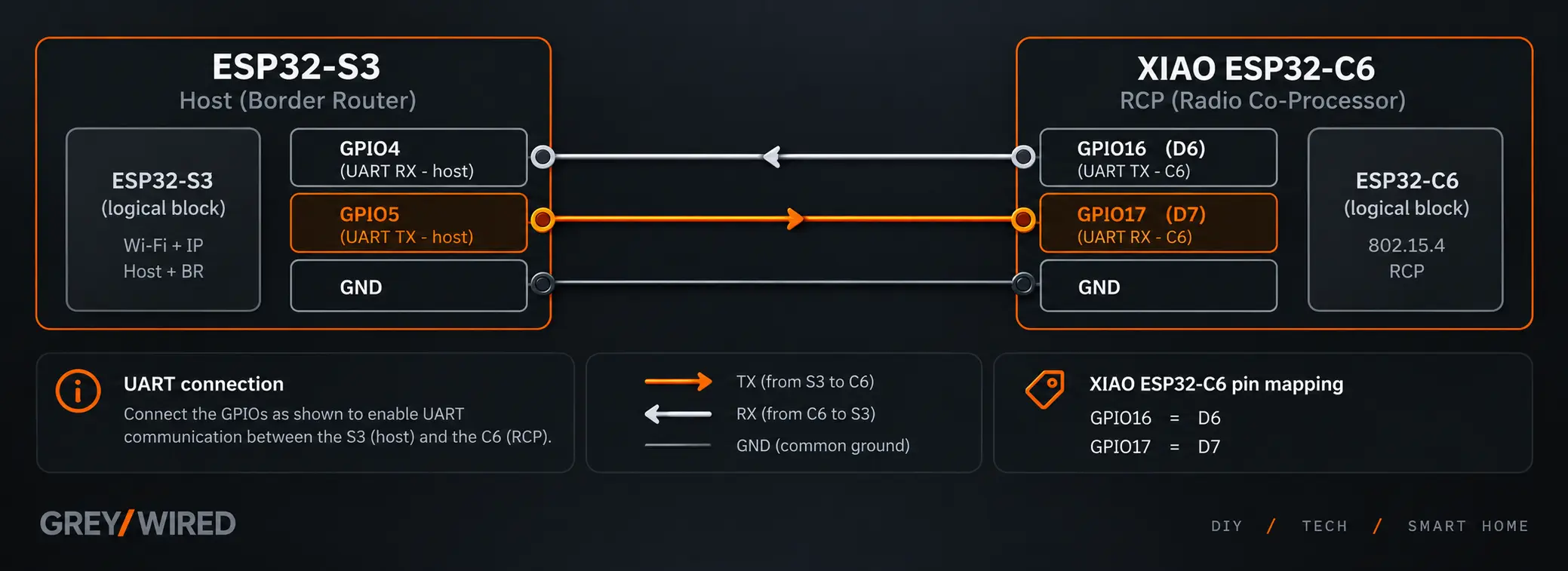
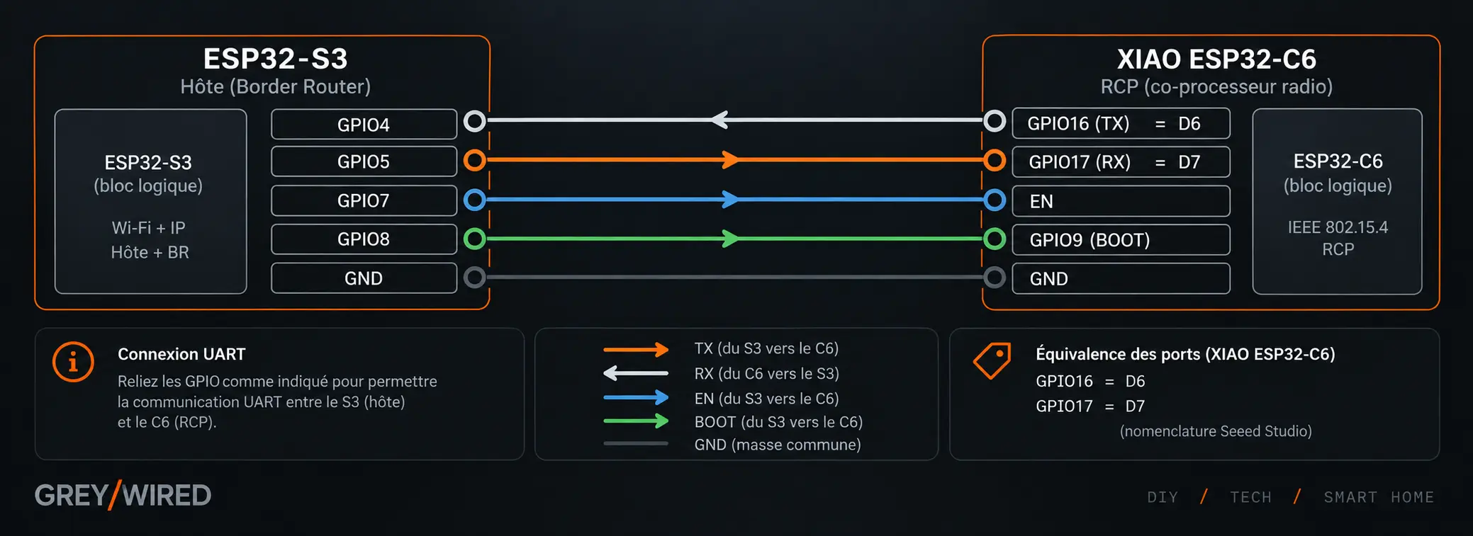
UART between the S3 and C6
My Spinel link uses:
CONFIG_PIN_TO_RCP_TX=4
CONFIG_PIN_TO_RCP_RX=5
In the host OpenThread configuration:
.rx_pin = CONFIG_PIN_TO_RCP_TX,
.tx_pin = CONFIG_PIN_TO_RCP_RX,
My wiring is therefore:
Letting the S3 update the C6
basic_thread_border_router has a particularly interesting mechanism:
the host can update the RCP firmware.
To do this, it must not only communicate with the C6 over UART, but also be able to control its reset and bootloader mode.
This requires two additional connections between the S3 and C6. Unlike the UART link, this part requires a couple of small solder joints on the XIAO ESP32-C6 to access the required signals on the board pads. It is not especially difficult with a fine soldering tip, but it is probably the most delicate hardware part of the build.
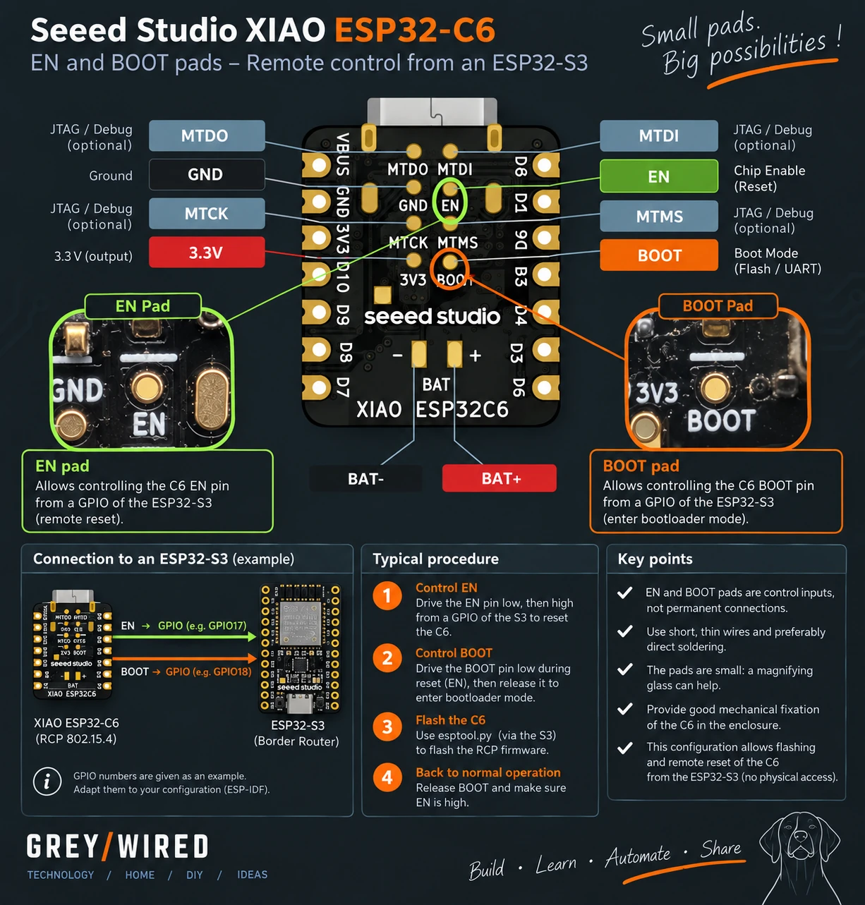
I therefore add:
S3 GPIO7  ──────────> C6 EN
S3 GPIO8  ──────────> C6 GPIO9 / BOOT
These two connections carry no Thread data. They are used solely by the S3 to control the BOOT/RESET sequence required when it needs to reflash the RCP firmware.
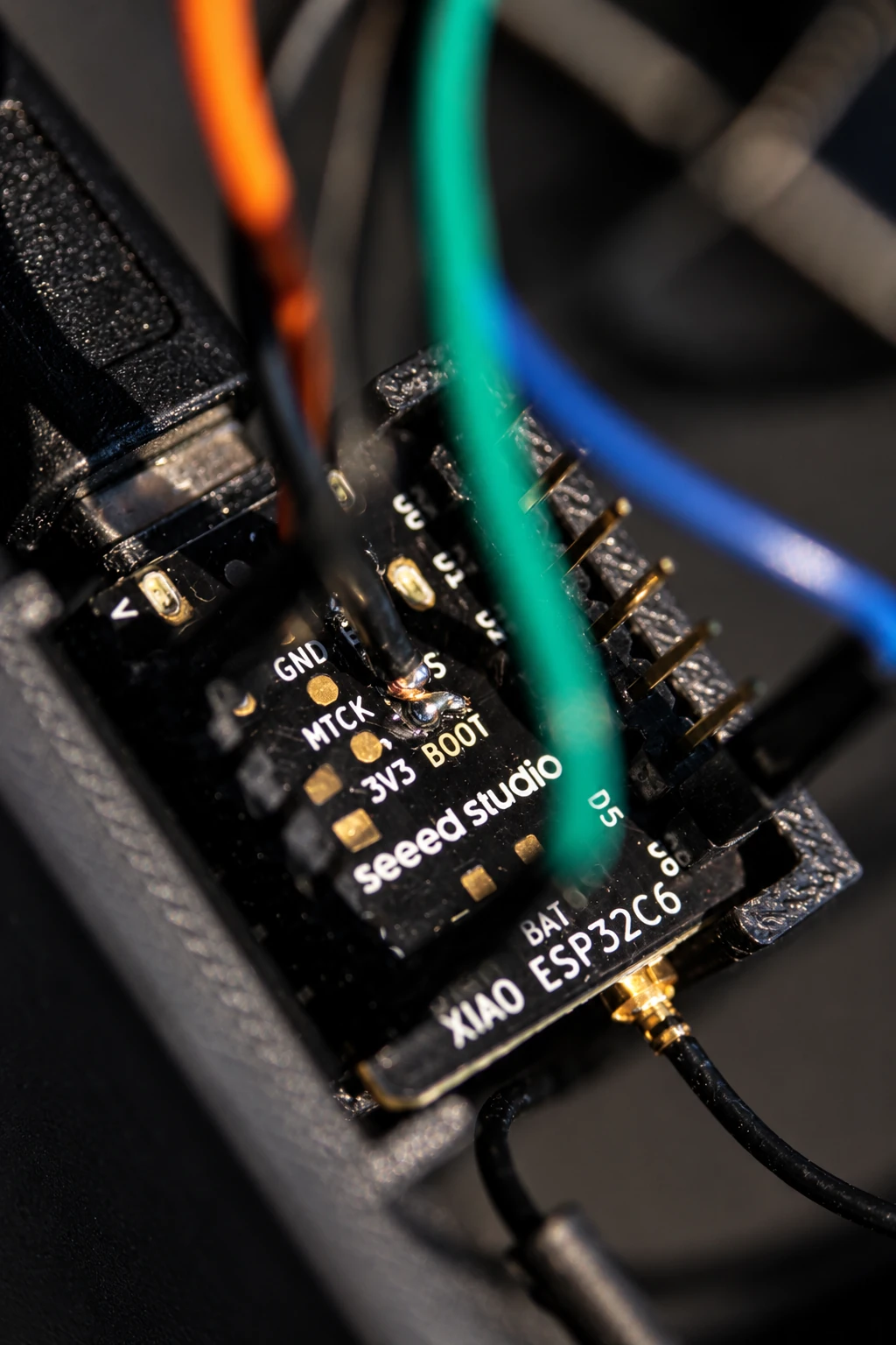
My complete connection then becomes:
And I enable:
CONFIG_AUTO_UPDATE_RCP=y
Where does the C6 firmware come from?
My configuration contains:
CONFIG_RCP_SRC_DIR="$ENV{IDF_PATH}/examples/openthread/ot_rcp/build"
CONFIG_RCP_PARTITION_NAME="rcp_fw"
CONFIG_RCP_PATH_NAME="rcp"
The Border Router therefore uses the artifacts already present in:
C:\esp\esp-idf\examples\openthread\ot_rcp\build
The chain becomes:
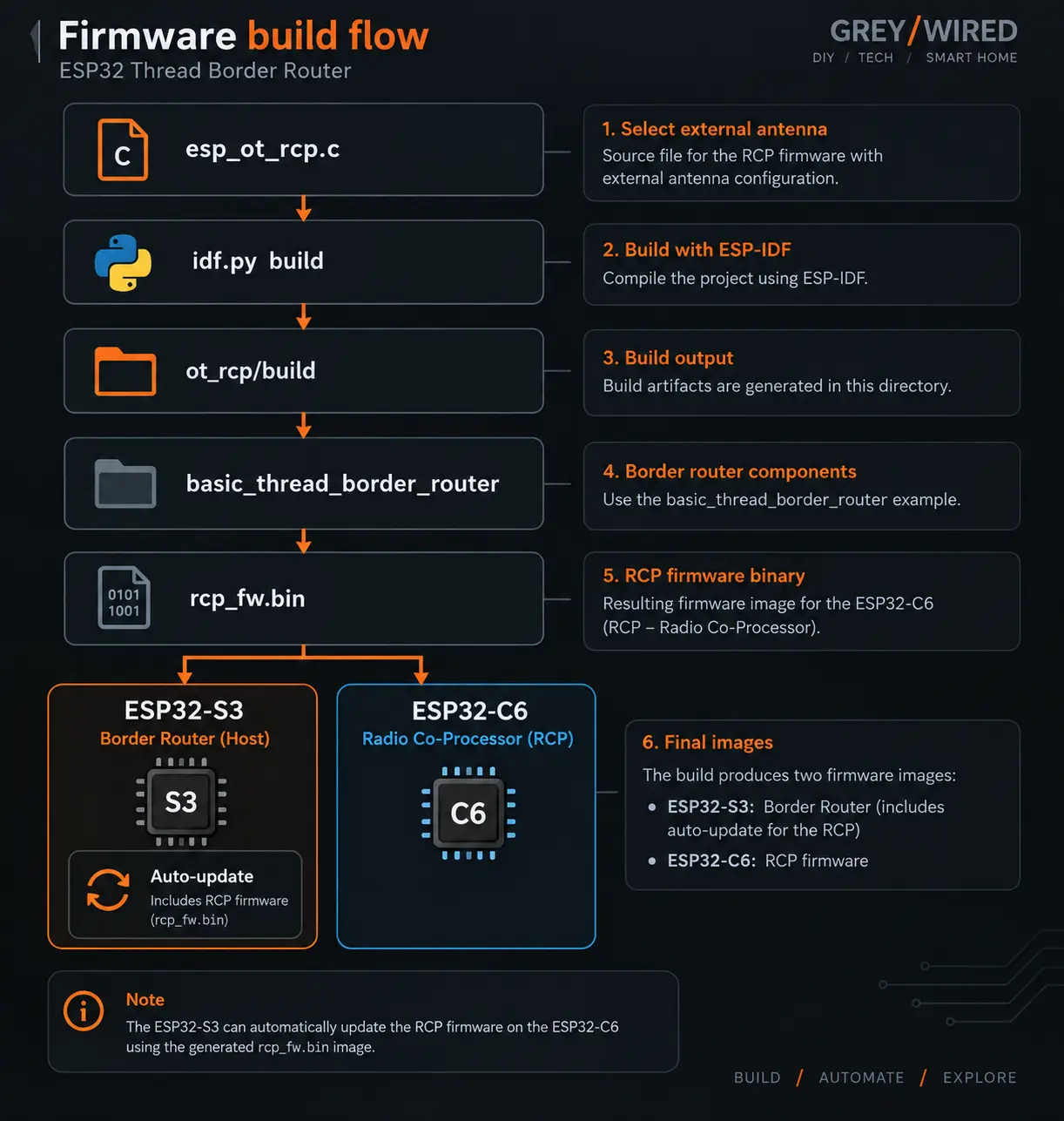
Most importantly, this means that my C6 firmware customization is preserved.
During my first migration, no C6 update occurred. The reason turned out to be very simple: the RCP firmware embedded by the S3 came from the same build as the one I had already flashed manually onto the C6.
The versions were identical. The auto-update mechanism therefore simply had nothing to do.
The following screenshots show the main menuconfig settings used on
the ESP32-S3 for this configuration: RCP selection, wiring to the C6,
Wi-Fi connection and reconnection, RCP update mechanism and USB
diagnostic console.


Flashing the new S3
The partition layout notably includes:
nvs         24K
otadata      8K
ota_0        2M
ota_1        2M
web_storage 200K
rcp_fw      640K
The rcp_fw partition contains the elements required to update the
radio co-processor.
After startup, the S3 correctly finds its C6 and the Border Router can operate.
All that remains is to give it back its old Thread network.
Restoring the existing Thread network
I inject the Operational Dataset that I backed up before the migration.
After activating it, I can verify:
ot dataset active
I recover the parameters of my original network, then:
ot state
returns:
leader
The new Border Router has therefore recreated the same Thread network.
But something is still missing: my IKEA devices.
Where did the devices go?
The first check gives:
ot child table
ot neighbor table
Both are empty.
Yet I had restored the correct dataset.
The answer was much simpler than expected: my test devices are battery powered. They were asleep.
After removing and reinserting the batteries in one of the devices, the nodes began to reappear.
A few moments later, ot neighbor table showed, among other things:
RLOC16 0xd801   Avg RSSI -55   LQ 3
RLOC16 0xd802   Avg RSSI -58   LQ 3
And ot child table returned:
0xd801
0xd802
I had therefore replaced the complete implementation of my Thread Border Router without recreating the network and without having to reinstall my test devices.
What I broke along the way
Seen from the end, the setup looks almost trivial: two ESPs, a few wires, two antennas, RCP firmware and Border Router firmware.
But to reach this version, I repeatedly broke something that worked. And almost every breakage taught me something.
The daily "crash"
I suspected the C6 before discovering that my Wi-Fi access point restarted every night and that my first implementation handled its return poorly.
The impossible-to-observe C6
I added a heartbeat and reset-reason logging to the firmware to determine what it was actually doing.
Migrating to a new Border Router
I learned that the network identity could be preserved through the Operational Dataset.
The devices that disappeared after migration
They had not forgotten the network. They were simply asleep.
The auto-update that updated nothing
It was working perfectly. The proposed firmware was simply the same version as the one already installed.
The external antenna
I also realized that it was not enough to think about the antenna currently used by the C6.
I had to make sure that the RCP firmware embedded for future updates also selected that antenna.
That is what led me to understand precisely the relationship between
ot_rcp/build, rcp_fw.bin and the auto-update mechanism.
If I had to do it again today
All this experimentation was useful.
But none of it is necessary to build the same Border Router today.
The procedure can now be summarized as follows:
- install ESP-IDF and
esp-thread-br; - build
ot_rcpfor the ESP32-C6; - configure its UART;
- select the external antenna if you use a XIAO ESP32-C6 with an external antenna;
- build
basic_thread_border_routerfor the S3; - select the C6 as the RCP;
- configure the UART link;
- optionally configure EN and BOOT to enable RCP auto-update;
- enable the Web UI and auto-start, then flash the S3 and C6;
- create a new dataset or import one from an existing network.
The final hardware result is simply:
And now that I have completed the S3 RF modification, it also has its own external antenna, this time for Wi-Fi.
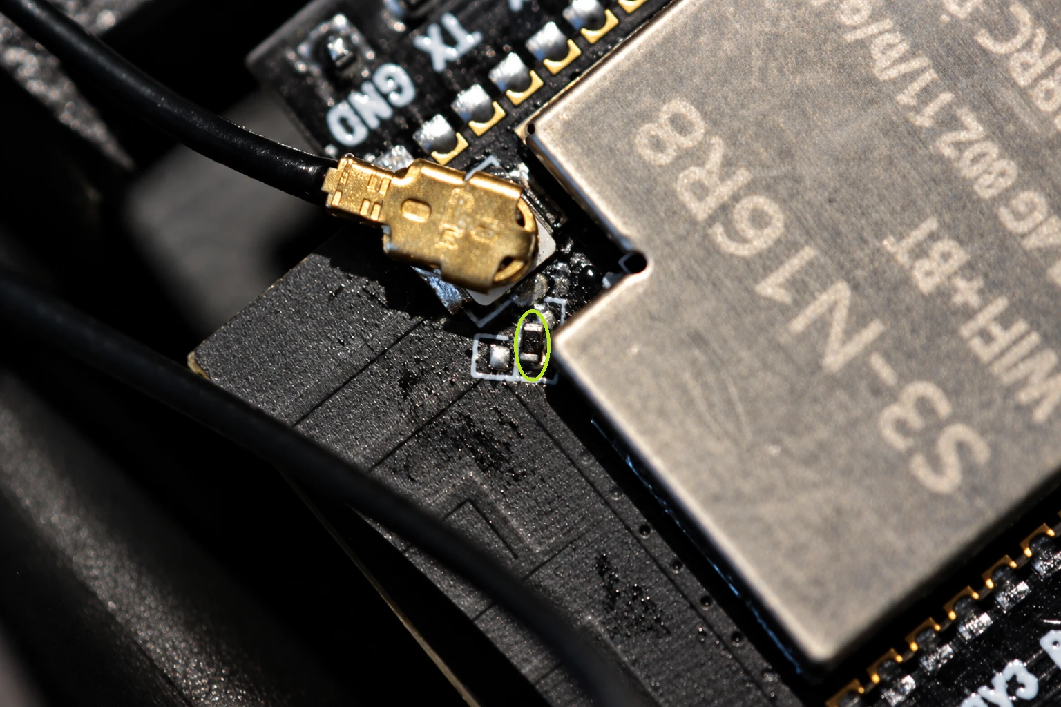
The two antennas therefore have completely independent functions:
S3 antenna  → Wi-Fi / IP network
C6 antenna  → IEEE 802.15.4 / Thread


So, why did I build it?
At first, I simply wanted to connect a lock over Thread rather than Wi-Fi.
That led me to build a Border Router around an ESP32-C6.
Then to replace it with an S3 paired with a C6.
Then to instrument the C6.
Then to want to add a small Web page.
Then to discover that Espressif now offered a much more complete implementation of what I had gradually been building.
And finally, to break my Border Router once again in order to migrate to this new architecture.
Yet the result is much more interesting than the original need.
I now have a Thread Border Router whose firmware I control, with a dedicated 802.15.4 radio, external antennas for Wi-Fi and Thread, a network observation interface, and the ability to automatically update its radio co-processor.
Most importantly, Thread is no longer really a black box.
I can inspect the Border Router's children, its neighbors, the quality of their links, their RSSI, their roles and the state of the network.
That is probably where the real answer to the question asked at the beginning lies.
Why build your own Thread Border Router?
Not because it is impossible to buy one.
Not necessarily because it will be better than a commercial product.
But because a consumer Border Router generally tries to make you forget that Thread even exists.
This one does exactly the opposite.
It lets you look at what is happening underneath.
And for someone who likes to understand how things work, that is probably the best reason to build one.
Updates
September 21, 2026 — Added a note about Wi-Fi reconnection and changed CONFIG_EXAMPLE_WIFI_CONN_MAX_RETRY from 6 to -1 to ensure persistent reconnection after an extended access point outage.
Comments
No comments yet.
Add a comment