
Planes, Decibels and an ESP32
At first, I simply wanted to know how much noise the planes were making. Then came an ESP32, a €15 Chinese module, an API, MQTT, a BME280, some 3D printing and a few unexpected twists. In short, a project perfectly under control.
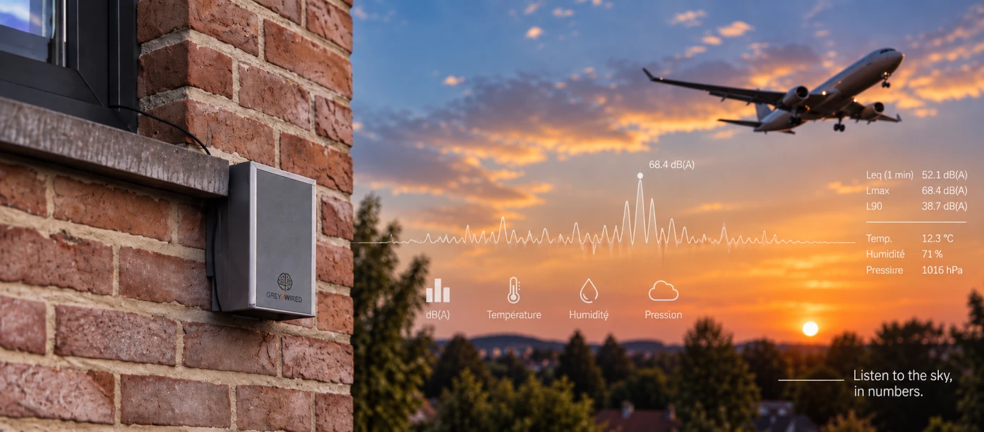
As part of my project to track the aircraft flying near the house, I had already managed to collect quite a lot of information.
I knew which aircraft had passed, when it had passed, at what altitude, how far it had been from the house...
But one essential piece of information was still missing:
how much noise had it actually made?
To answer that question, I didn't simply need a sound level meter.
I needed one that could stay outside, run continuously and, most importantly, automatically provide its measurements to my tracking system.
The requirements seemed fairly modest:
- measure sound levels properly;
- be able to remain installed outdoors;
- operate continuously;
- allow my tracker to retrieve the measurements automatically.
Nothing particularly exotic.
Or so I thought.
Buy something?
My first instinct was obviously to look for an existing solution.
I started with Amazon.
There are pages and pages of sound level meters. Small ones, large ones, ones with displays, ones with recording capabilities...
But a model I could install outside, leave running permanently and query automatically from my script?
Nothing.
Or at least, nothing I could find.
So I expanded my search to the rest of the Web.
And there I did start finding connected acoustic monitoring systems. The problem was that I was quickly entering the world of professional solutions, with prices that had very little to do with my small experimental project.
And this really was just an experiment.
Spending several hundred euros simply to answer a question I had asked myself out of curiosity didn't make much sense.
The final, almost unavoidable stop when looking for a slightly unusual sensor: AliExpress.
Same story.
Plenty of things related to noise measurement, a few interesting modules... but still not the obvious little box I had imagined:
put it outside, ask it for the sound level whenever I need it, and get an answer.
At this point, the DIY itch was obviously starting to kick in.
So...
I'll build it.
An ESP32, obviously
The ESP32 was a fairly obvious choice.
I regularly use them for all sorts of small projects. I even used one to build a densitometer to monitor the fermentation progress of a batch of beer.
For a few euros, you get Wi-Fi, UART, I²C, GPIO, more than enough processing power and an environment I already know.
All that remained was figuring out how to measure the noise.
The first idea was obvious:
an ESP32, a microphone, a few lines of code...
Surely it couldn't be that complicated.
A microphone doesn't measure
Except that after digging into the subject a little, I quickly realised that I was confusing two different things.
A microphone captures sound. By itself, it does not measure a sound level.
Getting an audio signal into an ESP32 is relatively easy. Detecting that a noise has occurred is easy too.
But what I wanted were values that actually meant something: something I could associate with an aircraft passing overhead and then compare with the next aircraft, or with the ambient background noise.
The amplitude obtained from a simple microphone module depends on the microphone itself, its preamplifier, gain, ADC, frequency response, mechanical installation...
And if I wanted something that even began to resemble a measurement in dBA, I would also have to deal with frequency weighting, calibration and signal processing.
In other words, I wasn't simply trying to build a noise detector.
I needed, at the very least, a foundation that actually behaved like a sound level meter.
So I went back to digging through the gigantic component drawer that is AliExpress.
Without really knowing what I was looking for.
The module with the ridiculously long name
Eventually, I stumbled across this:
“Industrial grade RS485 noise sensor module, noise sensor tester, decibel sound level meter, high precision noise detector, sound transmitter”
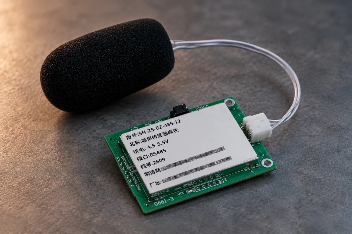
There.
At least as far as keywords were concerned, they had everything covered.
More seriously, the specifications started to look interesting.
Instead of merely providing the raw signal from a microphone, the module directly reports a sound level measurement with A-weighting, over a range of 30 to 120 dB.
It is available in several variants with different supply voltages and communication interfaces.
For my setup, I chose the 5 V UART TTL version, which is particularly well suited to use with an ESP32.
The manufacturer even claims an accuracy of ±0.5 dB at its 94 dB, 1 kHz reference point.
Let's be clear: I have absolutely no intention of blindly trusting an AliExpress datasheet, let alone claiming that this module turns my project into a professional measuring instrument.
But that isn't what I need either.
My goal is much more modest: obtain a reasonably consistent sound level measurement so I can observe what happens when an aircraft passes and compare different events.
Even taking the manufacturer's specifications with the appropriate amount of scepticism, this was beginning to look remarkably like a sound level meter.
And, most importantly, the module costs about €15 delivered.
At that price, the experiment was definitely worth trying.
Ordered.
First tests
Eventually, the module arrived and I could finally start testing it with an ESP32-S3.
To make everything work together, I used ESP-IDF 5.5.5.
Why that instead of Arduino, ESPHome or something else?
For an extremely scientific reason:
it was what I already had open.
At the time, I happened to be tinkering with an ESP32-based OpenThread Border Router. My ESP-IDF environment was therefore already installed, configured and running.
Might as well keep using it.
So I started vibe coding an initial firmware with my favourite AI.
Nothing particularly ambitious at first: get the module talking, understand what it returns and check whether the values appear usable.
And the first results were very encouraging.
Communication worked, the data came through cleanly and the values looked coherent.
Progress was quick.
The hack was seriously beginning to look like a solution.
One number doesn't tell the whole story
As I went further, however, I realised that a simple instantaneous noise measurement was rather limiting.
Sound levels constantly fluctuate.
A value retrieved at one particular moment might be captured just before an aircraft passes, right at its maximum, or a few seconds afterwards.
Ultimately, it doesn't tell you very much about what actually happened.
But that's hardly a problem.
Since the ESP32 is continuously receiving measurements from the sensor anyway, I might as well ask it to do a little more.
The firmware therefore began keeping a history and calculating several indicators over different time windows.
The idea was no longer simply to know how loud it is right now, but to describe a sound event and put it into the context of its surrounding environment.
At this point, I had everything I needed on the measurement side.
A small API
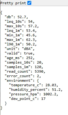
Now I needed to make the information accessible.
The next step was therefore to add a small HTTP API exposing the data as JSON.
Once again, a little vibe coding and the problem was quickly solved.
A simple request could now retrieve the current state of the sound level meter along with the various calculated values.
That was exactly what I needed: my tracking system could query the sensor whenever an aircraft passed and retrieve the acoustic data corresponding to the event.
The API is deliberately extremely simple.
There is no user account, token, API key or authentication mechanism.
That isn't an oversight.
The information being exposed consists simply of sound level measurements and, in my case, there is no particular reason for them to be confidential.
Adding authentication would mostly have made the systems retrieving the data unnecessarily more complicated.
The only indirect barrier is ultimately the Wi-Fi network itself: you need access to the local network to reach the ESP32.
But that is more a consequence of the architecture than an actual security measure intended to protect the sound level meter.
And while we're at it... Home Assistant
Since everything had been working surprisingly well up to this point, why stop there?
So I added MQTT publishing to the firmware, allowing the measurements to be integrated directly into Home Assistant.
Did I actually need my sound level meter to appear in Home Assistant?
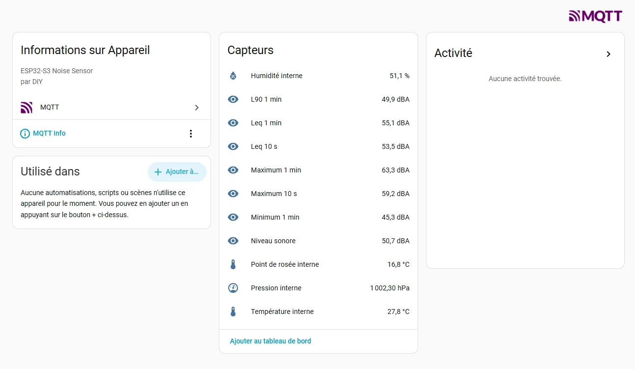
At that point, absolutely no idea.
But since MQTT was available and I have a tendency to centralise anything in the house that produces vaguely usable data in Home Assistant, adding it seemed logical.
I'd find a use for the data later.
Now I need to put all of this outside
The prototype was working well enough to start considering a permanent installation.
There was still one practical problem: power.
For a while, I considered an autonomous solution using a battery and solar panel.
On paper, it was appealing.
In practice, much less so.
The first problem was cost. A battery, charging electronics, a properly sized solar panel and everything else involved would probably have multiplied the cost of the project by four or five.
The second problem was reliability.
A battery permanently installed outdoors has to cope with cold, heat and sometimes significant temperature variations. It would have added a lot of uncertainty to a project that simply didn't need to be autonomous.
So a sufficiently long USB cable would do the job perfectly well.
Less elegant on a diagram, certainly.
But simple, cheap and probably much more reliable.
While thinking about the outdoor installation, however, another question started to worry me:
humidity inside the electronics compartment.
Humidity... or rather condensation?
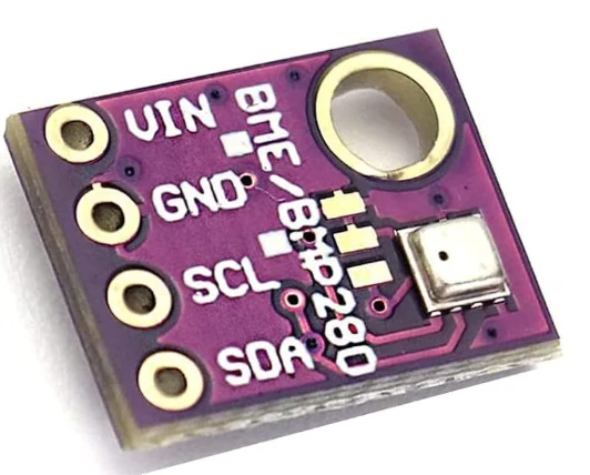
Rather than simply adding a humidity sensor, I decided to use a small sensor capable of measuring temperature, humidity and atmospheric pressure.
I chose the very common BME280.
It is inexpensive, easy to interface with an ESP32 and, with this kind of small module, I tend to order two or three at a time.
As we'll see, that habit can occasionally prove useful...
Temperature and humidity make it possible to calculate something much more interesting for my particular problem:
the dew point.
A quick return to vibe coding to integrate the BME280, calculate the dew point and add all of this information to the data already being exposed.
I also took the opportunity to add a small USB breakout board, making it easier to handle and power the S3 and the sound level meter module.
At this point, it was time to do something particularly difficult when you enjoy tinkering:
stop touching anything for a few days.
The system would run quietly for a while so I could check its stability.
In the meantime, I could work on the enclosure.
A 3D-printed home
The constraint was rather unusual.
The electronics needed protection from the weather, but the acoustic sensor itself needed to remain exposed to the outside air.
Completely sealing the microphone inside a watertight box would obviously have been rather counterproductive.
After a little brainstorming, 3D printing seemed like a good solution.
I could design an enclosure specifically around my constraints instead of trying to adapt an existing box.
A few sessions in Fusion 360 later, I had a first prototype that seemed to meet the requirements.
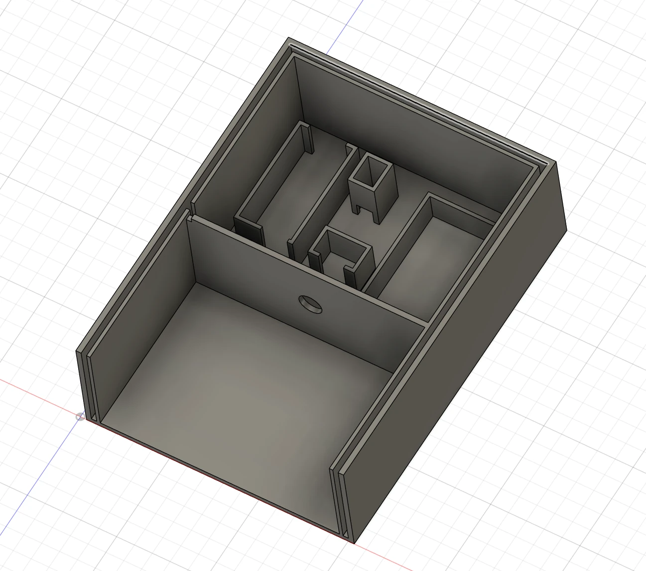
I chose a double-wall construction, with a separate chamber for the electronics.
The acoustic sensor remains in contact with the outside air, but is recessed far enough to be reasonably well protected from the weather.
And, of course, it keeps its windscreen.
The double wall is still relatively thin. I don't expect it to turn the enclosure into a thermos flask, but it might provide a little buffering against outside temperature variations.
We'll see.
Which filament?
For something intended to live permanently outdoors, ASA would probably have been the more rigorous choice, particularly because of its resistance to UV and high temperatures. ABS could also have been considered.
But I had absolutely no desire to turn this part of the project into another experiment.
I already had some Anycubic PETG on hand, I knew how to print it properly and its characteristics seemed more than adequate for this experiment.
So PETG it was.
Will it retain its properties and appearance perfectly after several summers, winters, freezing periods and days in full sun?
We'll see.
After all, the enclosure has now become an experiment too.
Designing for printing too
The print went perfectly and, more importantly, produced very little waste.
This is something I try to consider from the design stage: a 3D-printed part should also be designed with the way it will be printed in mind.
A small change in geometry can sometimes eliminate almost all supports.
And when a part becomes too complicated to print cleanly, it is often better to split it into several pieces designed to be assembled afterwards.
It takes a few extra minutes in Fusion 360, but saves filament, printing time and that wonderful activity known as tearing supports off a print for twenty minutes.
First, I printed the two main parts.
Then it was time to take the electronics out of their temporary setup and introduce them to their new home.
The S3, sound level meter module, BME280 and USB breakout all fit into the small recesses designed for them.
Those recesses are, incidentally, a double-edged choice.
They hold the various modules in place without requiring screws, standoffs or glue. On the other hand, the enclosure becomes dependent on the exact dimensions of the boards being used.
For a prototype, I'm perfectly happy with that compromise.
The complete assembly then went back into operation for a few more days to make sure everything remained stable in its new configuration.
And how do I attach this thing?
I still needed to figure out how to mount the enclosure outside.
One thing was certain:
I didn't want to drill through it.
Every hole would create another potential path for water or moisture.
So I designed a sort of large T-shaped piece with two long sliding slots, which is simply glued to the back of the enclosure.
Its large surface provides plenty of area for the adhesive and distributes the load nicely.
The mounting principle is extremely simple.
Two screws are installed in the wall where the sound level meter will be mounted, leaving their heads protruding slightly.
The enclosure is then positioned over them and the screw heads slide into the two slots.
The enclosure itself remains completely intact, and the whole assembly can be installed or removed in a matter of seconds.
Simple.
And then... nothing
So I glued the mounting rail to the back of the enclosure, powered everything back up...
And then:
nothing.
The S3 had power.
So did the sound level meter module.
But there was no ping, no API access, no data on the network.
A few minutes earlier, everything had been working perfectly.
My first suspect was obviously the Dupont wiring.
I checked it, moved the connections around a little...
Nothing conclusive.
So I switched to monitoring to see what the S3 was actually saying.
And that led to the first discovery:
the BME280 was no longer responding.
The second discovery was slightly more annoying:
the firmware really didn't like that situation.
The BME280 initialisation failure caused a crash, followed by a reboot that tried to initialise the BME280 again, failed, restarted...
A nice endless loop.
So I now had two problems to solve.
Why had the BME280 suddenly disappeared?
And, more importantly:
why had I allowed a completely optional sensor to take down the entire sound level meter?
Sometimes a failure can be useful
The priority was obvious: fix the firmware.
The absence of the BME280 had to be treated as a non-fatal error.
At worst, its data would be unavailable, but the S3 still had to keep running, measuring noise and exposing the sound level meter data.
Back to vibe coding.
A few changes later, the software problem was fixed.
I could unplug the BME280 without the rest of the system caring very much.
Perfect.
All that remained was figuring out why this particular BME280 stubbornly refused to work.
I still suspected the Dupont wires, so I checked the entire chain with a multimeter.
Everything looked normal.
I pushed the I²C bus diagnosis a little further.
Nothing conclusive there either.
The BME280 remained stubbornly absent.
And then I remembered that I had bought several of them.
I replaced the module.
Restarted.
Everything worked.
To make sure I hadn't simply stumbled onto a coincidence, I put the old BME280 back.
The problem returned.
I reinstalled the new one.
Everything worked again.
Right.
The verdict was clear enough: something was wrong with the first module.
Why?
No idea, for now.
So I put it aside with a small “Broken by...?” label.
Perhaps we'll subject it to a few experiments someday.
Still, this little failure had one useful consequence: it forced me to fix a genuine firmware flaw before the system went outside to live.
A lucky accident?
Dupont wires in a permanent installation?
There is another choice in this prototype that deserves to be acknowledged:
I kept the Dupont wires.
In terms of long-term reliability, this is clearly not an ideal solution.
The contacts can move, oxidise or eventually become intermittent. It certainly isn't how I would build a device expected to run for ten years without intervention.
But that isn't the goal either.
This is still an experimental prototype.
And the Dupont wires offer one very practical advantage here: every part of the assembly can be replaced in seconds.
The BME280 episode demonstrated that rather perfectly.
For this version, I am therefore deliberately choosing modularity and ease of experimentation over maximum mechanical reliability.
The wiring may not be worthy of an industrial control cabinet, but it isn't chaos either.
And, most importantly, everything remains accessible.
Shall we close it?
This time, the project was genuinely starting to look ready for the outdoors.
As a precaution, I slipped a few small packets of desiccant into the electronics compartment.
The BME280 will let me monitor what is actually happening inside, but I might as well improve the odds.
All that remained was closing the enclosure.
Originally, I had planned to seal it with silicone.
That would probably be effective.
It would also be rather annoying the day I wanted to open the enclosure again.
And since this is still an experimental prototype, the probability of needing to get back inside is not exactly zero.
So I decided to do something much less elegant:
Duct tape.
Easy to apply, easy to remove and probably good enough for the first tests.
I have a feeling I'm going to regret this choice.
But anyway...
And now, outside
This is where the project stands today.
The firmware is running.
The sound level meter module is measuring.
The API responds.
MQTT publishes its data.
Home Assistant receives it, even though I still don't know exactly what I'm going to do with it.
The BME280 monitors temperature, humidity, pressure and dew point.
The enclosure is printed.
A few packets of desiccant are waiting to find out whether their presence was actually necessary.


And now, we measure
The enclosure has finally left the workshop.
It is now mounted on the outside wall, the sound level meter runs continuously and its measurements are automatically available through the API and MQTT. Home Assistant also receives the sound level and the various statistics, along with the temperature, humidity and pressure measured inside the enclosure.


So this time, it isn't really a prototype sitting on a desk anymore.
There are obviously still things to observe.
The PETG enclosure will now have to deal with rain, sun, temperature changes and a few seasons outdoors. It will be interesting to see how it ages and how the internal temperature behaves when it is exposed to direct sunlight.
And, most importantly, all of this still has to be connected back to the question that started the project.
My aircraft tracker already knows their trajectory, altitude and distance from the house. It can now query the sound level meter as well.
The next time aircraft start passing at low altitude again, I will finally be able to put the two datasets side by side.
Which aircraft passed?
At what altitude?
At what distance?
And how much noise did it actually make?
That was the original question.
It only took an ESP32-S3, a Chinese sound level meter module, a BME280, a few lines of Modbus, an API, MQTT, a 3D-printed enclosure and a few perfectly reasonable detours to start answering it.
Comments
No comments yet.
Add a comment